Document ID: APP-D903
Public Compliance Release

ASTM D903 Test Guide: Peel Testing for Adhesives

Architecture
NEWTON™ 32-BIT

Application Details

Standard:
ASTM D903
Material Type:
Adhesives
Specimen Type:
Test Type:
Peel
Industry:
Adhesives
Mechanicaltest.org | Applications

The Challenge Gap

Flexible backing materials exhibit substantial parasitic elastic deformation and erratic unrolling behavior during 180-degree inversion tracking, leading to artificially elevated peak forces and severe data scattering.

The Solution

Utilize a dedicated 180-degree peel trailing sled alignment fixture paired with high-frequency electronic data filtering to isolate pure interface stripping energy.

Insight

Always discard the first 25mm of peeling data from calculations; adhesive failure must reach steady-state equilibrium before capturing valid averages.

Required Test Equipment for ASTM D903

Software

Driven by the Newton N-D903 software module to calculate the peel strip adhesion strength of adhesive bonds, tracking continuous peeling force profiles at 180 degrees.

Grips/Fixtures

Includes a motorized 90/180-degree sliding peel bed or standard high-stiffness manual side-action vise grips to ensure an exact orthogonal peeling path.

Extensometer

Employs an ultra-sensitive digital load cell interface to monitor continuous micromechanical peeling variations down to 0.01 N.

Insight

Always discard the first 25mm of peeling data from calculations; adhesive failure must reach steady-state equilibrium before capturing valid averages.

The Newton Advantage

High-fidelity controller sampling raw load data natively at 1000Hz while automatically executing multi-point stripping average algorithms over the active tracking zone.

Expert Engineering Commentary

Core Problem Identification

Substrate tearing prior to adhesive line separation, or localized slip-stick oscillations producing an uninterpretable saw-tooth load curve.

Root Cause Analysis

Inadequate or uneven adhesive layer curing profiles, or selecting a flexible backing material with lower ultimate tensile capability than the bond’s inter-facial shear capacity.

Hardware Specific Solutions

Single-column electromechanical materials test system equipped with a 1kN load cell and lightweight pneumatic side-action grips featuring smooth rubber face inserts.

Mechanics & Specimen Behavior

Primary Mechanics

Continuous 180-degree peeling or stripping mechanical action applied across a partially bonded laminate assembly.

Specimen Details

Rectangular substrate coupon measuring 25mm wide by 300mm long, consisting of a flexible material bonded to a rigid plate or a secondary flexible ribbon.

Mechanical Ratios & Properties

Stripping separation rate maintained strictly at 152 mm/min (6 in./min) across a fixed 127mm tracking window to ensure stable inter-layer cleavage dynamics.

Additional Commentary

180-degree peel tests quantify real-world stripping resistance for flexible laminates, but results are highly dependent on the thickness and stiffness of the backing substrate.

Pro Tip

Ensure the unbonded trailing tail of the flexible strip is turned back at exactly 180 degrees and aligned coaxially with the primary crosshead load line to eliminate vertical vector skew.

Common Pitfalls

Failing to maintain a perfectly clean, uniform adhesive thickness during curing, which results in extreme slip-stick load fluctuations and invalid average data.

Analysis & Calculation Standards

Event & Failure Detection
Initial cleavage initiation threshold, peak peel force transition tracking, and steady-state stripping data-window limits.
Required Calculations
Average Peel Strength (load per unit width), Minimum Stripping Force, Maximum Peak Peel Resistance, Total Energy Dissipation.
Statistical Outputs
Batch summary logs reporting mean peel resistance limits, standard deviation distributions, and specific inter-facial failure mode classifications.
Let's Find the Right ASTM D903 Equipment for Your Application

The Newton™ 32-Bit
Difference

Typical testing system controllers rely on 24-bit resolution. Under high-accuracy flexural analysis, this creates a data phenomenon called **”stair-stepping”** or quantization error. When trying to track minor micro-deflection in rigid polymers, 24-bit electronic circuits suffer from resolution limits, dropping critical transition points during initial load curves.

Newton Characterization™ architecture utilizes a 32-bit analog-to-digital processor converter. This increases measurement fidelity by a factor of 256x, outputting 4.29 billion discrete signal thresholds. Electrical chatter is actively muted under a dedicated 100,000:1 Signal-to-Noise Ratio (SNR).

Simulate Signal Mode

Real-Time Continuous Sampling Simulation

Comparing standard 24-bit quantization with Newton™ 32-bit resolution

Observe the stepped resolution blocks in the legacy 24-bit curve (Red) versus the absolute **analog-smooth response curve** captured by Newton™ 32-bit architectures (Green). This fidelity is what prevents mechanical data variance during modulus evaluation.

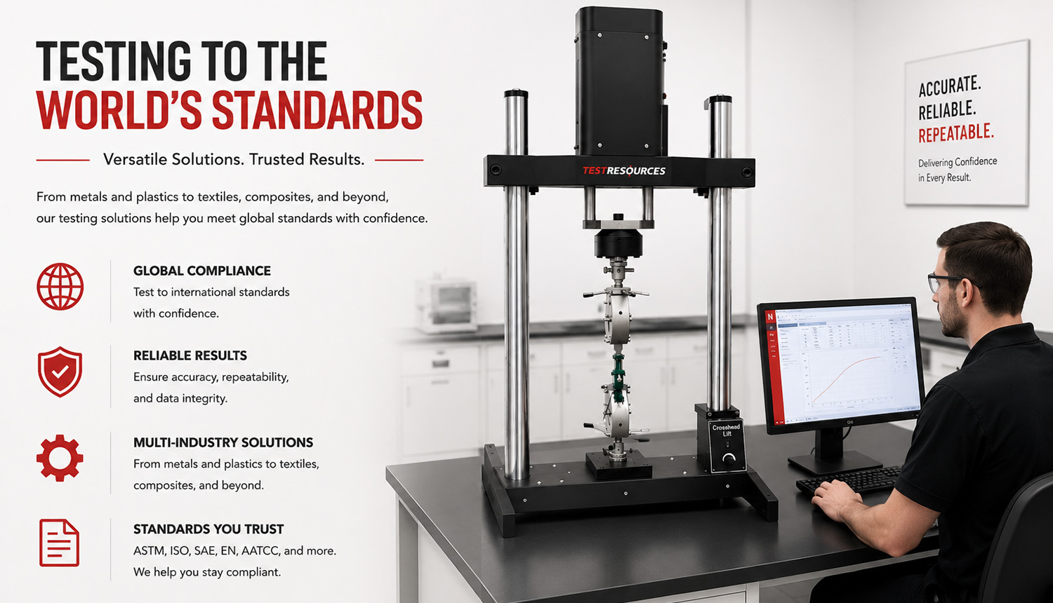
Machines CTA

Start the Conversation

The best testing solutions start with a conversation, not a catalog - backed by five decades of engineering expertise.

Name
Name